Gas Burners

Home / Products / Gas Burners

GAS BURNER 1562

Call our Experts
Gas Burner 1562

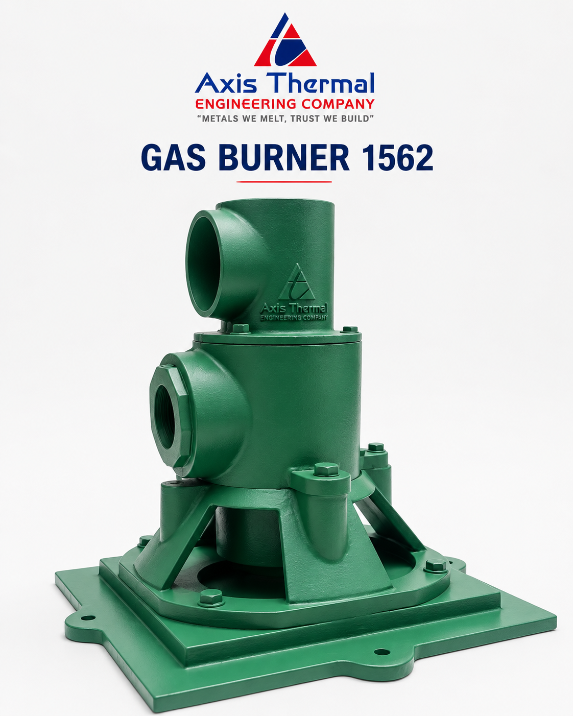
1562 Gas Burners are designed to give maintenance-free operation using heavy oil, light oil, or gas. There are no “Superfluities” on this burner—it has a heavy cast iron body of clean design that avoids clogging even when used on tough jobs such as forge furnaces fired with heavy oil.

Burner Competency

The total air capacity of the burners is listed under list I for single blower supplying at 20”wg combustion air and 22”wg atomizing air for light oil operation and 22”wg combustion air and 38”wg atomizing air for heavy furnace oil operation. Use list II and III when selecting separate blowers for combustion and atomizing air. For sizing blowers or burners at other pressures, add figures from the List II and III to get total capacity.

Capacities shown in list II is for operation on gas with the air shuttled closed. On oil operation these capacities are increased 20% the additional air supplied through the atomizing air connection. When burning either gas or oil with the shutter open, burner capacities may be doubled if furnace conditions assure sufficient secondary air.

Functions Of The Burner

Oil with a viscosity of 70 to 90 seconds Redwood I and a pressure between 25 and 30 psi, should be supplied to an Air/Oil ratio controller which will deliver oil to the burner at a pressure proportional to the main air pressure, thus maintaining the correct air/oil ration at all firing rates. The atomizing air pressure at the burner may be as low as 21”wg when using distillate oil, 38”wg when using heavy oil.

The 1562 burners can operate on any gas of 2000 to 12800 kcal per cu.ft heating value. Switching from gas to oil operation or oil to gas may be done quickly without furnace shutdown, simply by turning off one fuel valve and opening the other.

Burner Assembly

The heavy cast iron body can stand much abuse. All internal parts of the 1562 burner are machined. The smooth surfaces stay free of oil deposits and dirt, thus greatly minimizing the need for cleaning, oil is, put though the burner in a straight passage having a large cross-sectional area permitting visual inspection for clogging and easy clean out if necessary. The burner oil valve is a non-plugging V-port oil valve which produces small and uniform flow rate changes throughout the 180°C sweep of the control handle.

EXCESS AIR GAS BURNER 1422

Call our Experts
Excess Air Gas Burner 1422

1422 Excess Air Gas Burners are commonly used on heat treat and nonferrous melting furnaces, kilns, ovens, air heaters, dryers, chemical process equipment, and other applications where superior temperature uniformity is required.

Performance From Fuel Rich To Xces Air With Low NOx Emissions

These sealed-in, nozzle-mix burners are stable over a wide range of air/gas ratios from large amounts of Xces air, to stoichiometric (chemically correct air/gas ratio), up to 50% Xces fuel (provided additional air for combustion is supplied to the furnace near the burners). Burners can be ignited at rich, lean, or correct air/gas ratio, then immediately turned to high fire. NOx emissions are low for all air/gas ratios. The most common ratio control system for 1422 Burners uses a cross-connected regulator. When appropriate for the application, fully metered flow systems and fuel only control are very satisfactory. Required gas pressures are low: 2”wg at burner for coke oven gas, less for natural gas.

Advantages Of Xces Air

Xces air can improve temperature uniformity by avoiding hot spots in front of burners, by churning furnace atmosphere to reduce stratification, and by creating positive furnace pressure to eliminate cold air infiltration. Xces air can give very high effective burner turndown. Thus, a furnace used for high temperature work (such as heat treating at 1000° C with burners firing on stoichiometric air/gas ratio can also be used for low temperature jobs (such as drawing or drying at 300° C) with burners firing on lean (XcesAir) air/gas ratio. There is a potential increase in fuel consumption because of heating extra air. The benefits, such as better products from improved heating, far outweigh the small increase in fuel costs.

Application Temperature

The 1422 burners can be used with chamber temperatures up to 1100° C. If furnace temperature could rise above 850° C after shutdown, some air should be maintained through the burner to prevent overheating.

Standard Construction

Burner bodies are heat resistant cast iron with Inconel air tubes. Mounting plate and tile assembly can be separated from the burner body for installation convenience. Air and gas connection orientation can be rotated in 90° intervals.

When reassembling the burner, the pilot and flame detector notches in the tile and mounting must be in proper alignment with the pilot and flame detector connections on the burner body. Burner is complete with cast iron mounting plate and 9" long 1500° C castable burner tile which must be supported and sealed in a hard refractory furnace wall. (See page 2 for optional construction suitablefor fiber lined furnaces.) When the furnace wall is thicker than the tile length, the tunnel beyond the end of the burner tile should be flared at a 30° or greater included angle, starting at the OD of the tile.

FIRE ALL GAS BURNER - 1514

Call our Experts
Fire All Gas Burner 1514

These hardy nozzle-mix burners have been used for many years on high temperature furnaces such as those for forging steel, melting aluminum or brass, and reheating steel bars or ingots...and on low temperature ovens and air heaters. Their sealed-in construction allows maximum efficiency through close control of air/gas ratio, furnace atmosphere, and furnace pressure—all contributing to better product quality. 1514 Fire All Burners, as the name suggests, are appropriate for an extensive industrial heating applications. Nominal capacities range from 6 to 84 mkcal/hr.

Combustion Performance

1514 Burners are better with 200% or more excess air. They may also be operated with excess fuel without forming carbon if additional combustion air is available in the furnace near the burner. Excess fuel limit with heavy oil is 50% as atomization deteriorates at richer ratios. Burners can be turned down to atomizing air only, but stability limits vary depending on burner size, grade of oil, and furnace atmosphere. For prolonged operation on atomizing air only in furnaces over 1200° C specify an alloy burner nose. Burners are suitable for some preheated combustion air applications (up to 350° C). Oil viscosity at the burners should not exceed 90 seconds R.W.I; oil pressure at the Ratio controller should be between 25 and 30 psi. Minimum atomizing air pressure at the burner is 24”wg for light oil, 42”wg for heavy oil.

Burner Blocks/Installation

Burner blocks are cast refractory rated for 1500° C furnace temperature. They are replaceable in the field, except for the 1514-10A whose mounting must be returned to the factory for burner block replacement (or purchase a spare mounting plate with a burner block cast onto it). Burner blocks should be supported securely in the furnace wall by a layer of castable refractory (not insulation) at least 9" thick all around the burner block, extending back to the furnace shell and securely anchored to it. For furnace walls thicker than the length of the burner block, the tunnel beyond the end of the burner block should be flared 30-45° from the center line, starting at the OD of the burner block.

Jacketed Burner Blocks

1514 Burners are available with support jackets around the burner block for applications where the burner block is not supported by furnace refractory. Jackets are available in three different metals and have maximum temperature ratings for each. They must be protected with sufficient insulation so as not to exceed rated temperature. Maximum temperature rating for jacket metals depends upon frequency of heat-up/cool-down cycles. As an example, batch annealing furnaces that are heated and cooled every day should use the “intermittent exposure” ratings. Continuous annealing furnaces that remain at the same temperature for months at a time, can use the higher “continuous” rating.

HF BURNER - 001

Call our Experts
HF Burner 001

Hot Air Burners are used on steel reheat furnaces, glassmelters, non-ferrous melters, rotary calciners, and other applications where low velocity luminous flames are desired. They use combustion air at temperatures up to 600°C. They burn gases of 2000kcal/scf or higher and light or heavy fuel oils.

Gas As A Fuel

001 Burners provide soft luminous flames when burning natural or coke oven gas in large open furnaces, such as slab or billet heaters. Flame shapes depend on forward velocity of the burning gases. Although rated nominally at 4.5"wc (550°C) air, flames tend to develop full length at combustion air pressures of 2-3"wc at theburner.

Gas flames are stable when starting with ambient temperature combustion air in cold, tight chambers; but well defined flame shapes may not develop until air is over 200°C. For stoichiometric firing, required natural gas pressure at the burner varies from approximately 60% of main air pressure with 10°C air to approximately 25% of air pressure with 550°C air. Retract the oil atomizer during gas operation.

Oil As A Fuel

Standard 001 Burners use high pressure “tip emulsion” atomizers with 5 to 6 kg/cm2 steam or compressed air. Resultant clean, highly luminous, well-defined flames are slightly shorter than natural gas flames. Heavy oils (#4 through #6) must be heated to reduce viscosity to 100 SSU or less at the burner. This atomizer is highly efficient, consuming less than 5kg/cm2, or 20ft 3 of 80 psi air of #6 oil burned. (Lower firing rates reduce this efficiency somewhat.) Are liable low pressure atomizer, using 40-70”wg cold air suppliedby a turbo blower, is available for most grades of oil when steam or compressed air is unavailable.

Control Systems

001 Burners operate from 0.2"wc main air pressure to 10"wc or higher. High fire air rate usually is between 2"wc and 6"wc. Input and air/fuel ratio controls should be selected and engineered for the range ability required. If combustion air temperatures vary considerably during normal operating cycles, metered flow control with air temperature compensation is recommended. When combustion air can be metered on the cold side of the recuperator, it may be acceptable to use differential pressure balanced ratio regulator. However, recuperator leakage can cause significant distortions and variations in air/fuel ratio when “cold lead metering” is used. ATEC field engineers are qualified to recommend the system most suitable for each application.

Ignition And Flame Supervision

A Pilot assembly is normally used to light the burner. Ignition sequence should provide for low fire start between 0.2 and 1.0"wc main air pressure. Pilot mixture pressure should be 3"wc or more. The Honey well UV detector has been tested on 001 Burners.

Need Help with Reliable Industrial Furnaces, Blowers and Burners?

Get In Touch